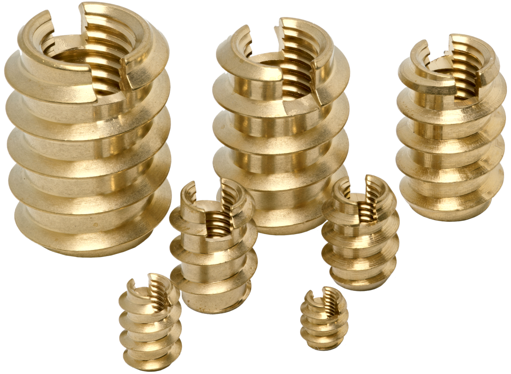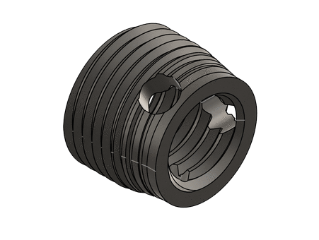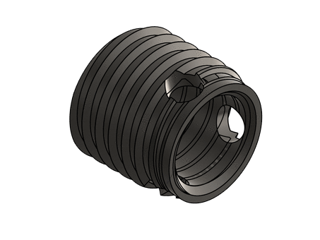
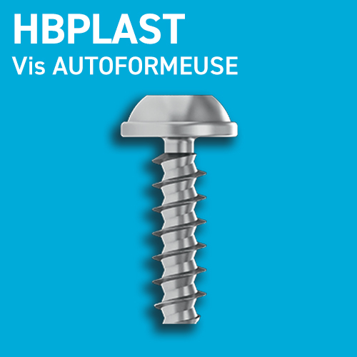
Insert réversible avec forme hexagonale d’entrainement (H) combinée au filetage intérieur. Filetage extérieur innovant autoformeur pour thermoplastiques, thermodurcissables et mousses hautes densités.
 ECO-CONCEPTION
100 % RECYCLABLE
Insert réversible avec forme hexagonale d’entrainement (H) combinée au filetage intérieur. Filetage extérieur innovant autoformeur pour thermoplastiques, thermodurcissables et mousses hautes densités.
ECO-CONCEPTION
100 % RECYCLABLE
Ingénierie des fixations
Grandes Séries – E-Shop
* à mi-hauteur de l’insert
** tendre PP, PE à moyen
*** dur PA66/GF40, PPA/GF30, PPS GF40, plastiques amorphes et thermodurcissables
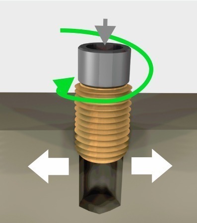
L’outil de pose met en place l’insert suivant son axe dans le puits de moulage ou le trou de perçage.
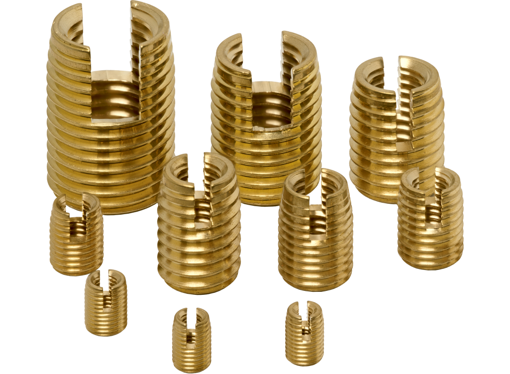
Auto formeur: la matière est refoulée sans faire de copeaux.
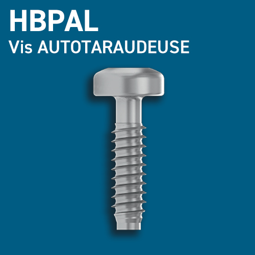
Auto taraudeur: la fente coupante coupe la matière.
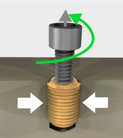
Le contre-écrou ou le mécanisme de l’outil de pose permet la séparation de l’outil et de l’insert. La matière comprime l’insert et assure la tenue.
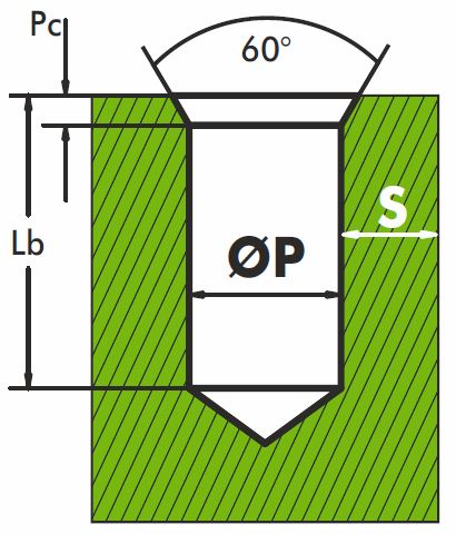
Lb Profondeur du puits :
Permet le logement des copeaux induits lors de l’installation.
Longueur de l’insert +2 à 3 mm
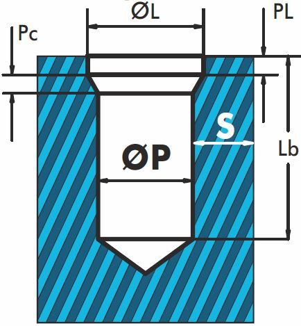
L’insert doit être entièrement noyé dans la matière :
Longueur de l’insert +1 mm
L’insert doit être entièrement noyé dans la matière :
Longueur de l’insert +1 mm
ØL =Øext+0.2 à 0.4 mm
PL =1 à 1.5 x pas filet ext
Pc =1 à 1.5 x pas filet ext
Un trou plus large facilitera la mise en place de l’insert au détriment de la résistance à la traction et à la rotation. Prévoir un lamage et/ou un chanfrein pour faciliter la mise en place de l’insert et avoir une pose finale optimale avec la surface de la matière.
Elle dépend de l’élasticité de la matière et de la contrainte sur le montage.
Plastiques Grande Diffusion : S ≥ 0.25 à 0.9 Ø extérieur de l’Insert
Plastiques Techniques
& Haute Performances
& Alliages Légers : S ≥ 0.2 à 0.6 Ø extérieur de l’Insert
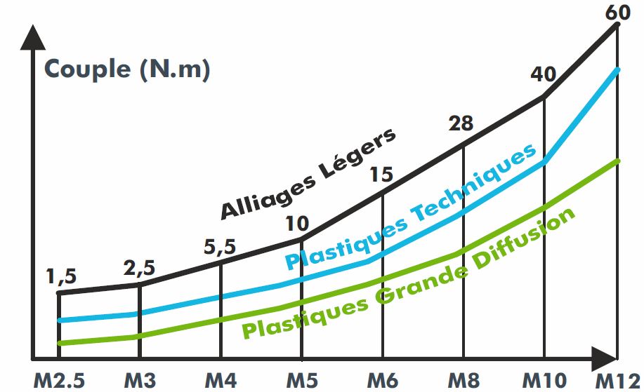
| Filetage Intérieur | M2.5 M3 | M4 M5 | M6 M8 | M10 M12 | M14 M16 |
| Vitesse de rotation en tr/min | de 800 à 1300 | de 600 à 900 | de 400 à 700 | de 300 à 450 | de 240 à 350 |
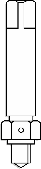

Monter un tourne à gauche sur la partie entraînante de l’outil.
Monter l’insert sur l’outil, fente ou trous coupants vers le bas.

Engager l’insert avec une légère pression en début d’installation pour former correctement les premiers filets.


En fin de montage, l’insert doit pénétrer de 0,1 à 0,2 mm.
(± 1/4 de tour) en dessous de la surface de la pièce.

A l’aide d’une clé, bloquer le contre-écrou et dévisser le tourne à gauche pour désolidariser l’insert de l’outil.
Le goujon de l’outil se place au milieu de la fente coupante pour ne pas bloquer le dégagement des copeaux de coupe
| Référence | Ø intérieur insert | Dim. du carré en mm | D2 Ø queue en mm |
|---|---|---|---|
| OVM 025 CM 0050 A 0 | M2,5 | 5 | 6 |
| OVM 030 CM 0050 A 0 | M3 | 5 | 6 |
| OVM 040 CM 0050 A 0 | M4 | 5 | 6 |
| OVM 050 CM 0080 A 0 | M5 | 8 | 10 |
| OVM 060 CM 0080 A 0 | M6 | 8 | 10 |
| OVM 080 CM 0080 A 0 | M8 | 8 | 10 |
| OVM 100 CM 0127 A 0 | M10 | 12,5 | 16 |
| OVM 120 CM 0127 A 0 | M12 | 12,5 | 16 |

Régler la butée de profondeur de façon à ce que la face d’appui de l’outil pénètre de 0,1 à 0,2 mm en dessous de la surface de la pièce.

Poser l’insert sur le puits.
Fente ou trou coupant vers le bas.
Engager avec une légère pression.
Visser sans pression.


Inversion du sens de rotation en fin de montage.
La goupille par effet mécanique (choc) désolidarise l’outil de l’insert.

| à Queue Cylindrique + carré d’Entrainement | à Queue Hexagonale 1/4” (6,35 mm) | |||
|---|---|---|---|---|
| Référence | Ø intérieur insert | Dim. du carré en mm | D2 Ø queue en mm | Référence |
| OVA 020 CM 0063 A 0 | M2 | 6,35 | 8 | OVA 020 HM 01/4 A 0 |
| OVA 025 CM 0063 A 0 | M2,5 | 6,35 | 8 | OVA 025 HM 01/4 A 0 |
| OVA 030 CM 0063 A 0 | M3 | 6,35 | 8 | OVA 030 HM 01/4 A 0 |
| OVA 035 CM 0063 A 0 | M3,5 | 6,35 | 8 | OVA 035 HM 01/4 A 0 |
| OVA 040 CM 0063 A 0 | M4 | 6,35 | 8 | OVA 040 HM 01/4 A 0 |
| OVA 050 CM 0100 A 0 | M5 | 9,53 | 12,5 | OVA 050 HM 01/4 A 0 |
| OVA 060 CM 0100 A 0 | M6 | 9,53 | 12,5 | OVA 060 HM 01/4 A 0 |
| OVA 080 CM 0100 A 0 | M8 | 9,53 | 12,5 | OVA 080 HM 01/4 A 0 |
| OVA 100 CM 0127 A 0 | M10 | 12,70 | 16 | OVA 100 HM 01/4 A 0 |
| OVA 120 CM 0127 A 0 | M12 | 12,70 | 16 | – |

| Outil Complet | Composants Outils pour achat au détail | ||
|---|---|---|---|
| Référence | Ø intérieur insert | Référence porte Embout | Référence Embout |
| OVK 030 HM 01/4 A 0 | M3 | PORTE-OVCOM | EMBOUT-OVCOM3 |
| OVK 040 HM 01/4 A 0 | M4 | PORTE-OVCOM | EMBOUT-OVCOM4 |
| OVK 050 HM 01/4 A0 | M5 | PORTE-OVCOM | EMBOUT-OVCOM5 |
| OVK 060 HM 01/4 A 0 | M6 | PORTE-OVCOM | EMBOUT-OVCOM6 |
| OVK 080 HM 01/4 A 0 | M8 | PORTE-OVCOM | EMBOUT-OVCOM8 |

| Outil Complet | Composants Outils pour achat au détail | ||
|---|---|---|---|
| Référence | Ø intérieur insert | Référence Embout | |
| OVH 030 HM 01/4 A 0 | M3 | – | EMBOUT-OVCOM3 |
| OVH 040 HM 01/4 A 0 | M4 | – | EMBOUT-OVCOM4 |
| OVH 050 HM 01/4 A0 | M5 | – | EMBOUT-OVCOM5 |
| OVH 060 HM 01/4 A 0 | M6 | – | EMBOUT-OVCOM6 |
| OVH 080 HM 01/4 A 0 | M8 | – | EMBOUT-OVCOM8 |

Produit |
Sous Famille |
Type |
Taraudage |
L |
Forme Extérieure |
Ø E |
Matière |
Spécification |
|||||||
Exemple |
I |
V |
H |
0 |
3 |
0 |
0 |
6 |
0 |
M |
0 |
5 |
0 |
L |
0 |
|
Insert |
à Visser |
non fendu filetage ext. 60° pas métrique ISO |
Taraudage intérieur |
Longueur totale 6 mm |
Filetage Métrique |
Diamètre extérieur 5 mm |
Laiton |
Aucune |
|||||||
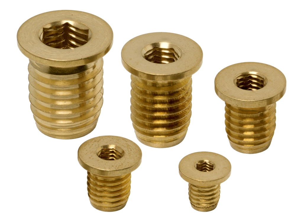
| Sous Familles V à Visser |
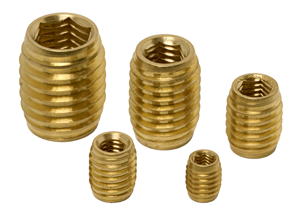
Type d’insert à Visser K avec tête et filet 45° à fond 160° – réversible + hexagone inter H sans tête et filet 45° à fond 160° – réversible + hexagone inter |
Matières |
Spécifications 0 Aucune N Nickelage |


SECAM vous accompagne depuis plus de 50 ans dans la conception et l’industrialisation d’inserts pour plastiques, alliages légers et bois, avec plus de 300 références disponibles en stock.
SECAM vous accompagne depuis plus de 50 ans dans la conception et l’industrialisation de vos vis pour matières plastique et alliages légers. Nous disposons d’une gamme complète de plus de 700 références disponibles en stocks.
SECAM est votre partenaire depuis plus de 50 ans pour la conception et l’industrialisation de vos inserts pour plastique, alliages légers et bois. Nous disposons d’une gamme complète de plus de 300 références disponibles en stocks.