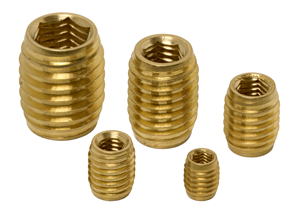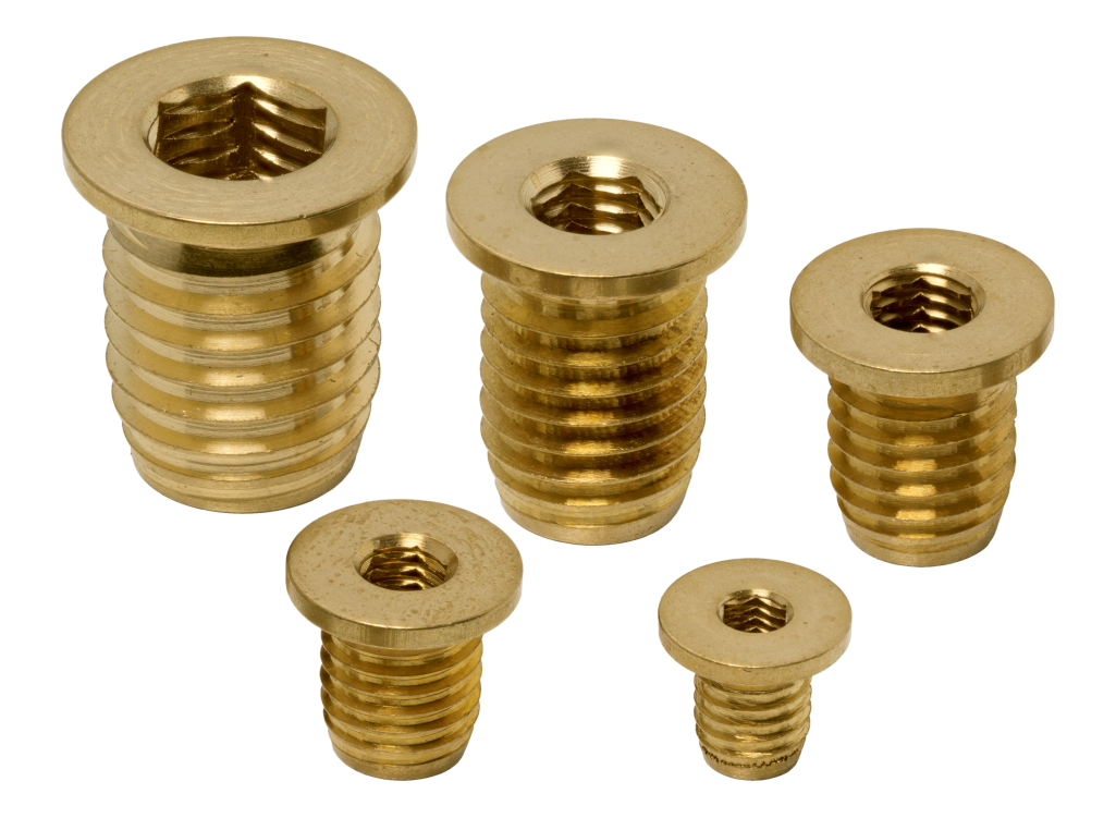

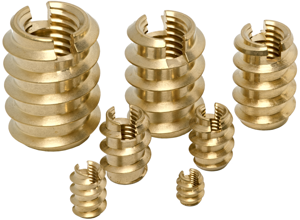
Post-molding installation
High tear resistance
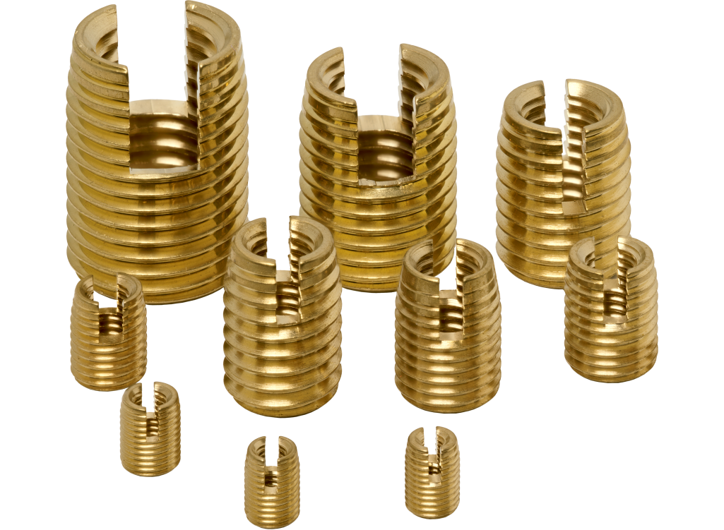
Self tapping
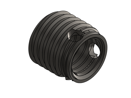
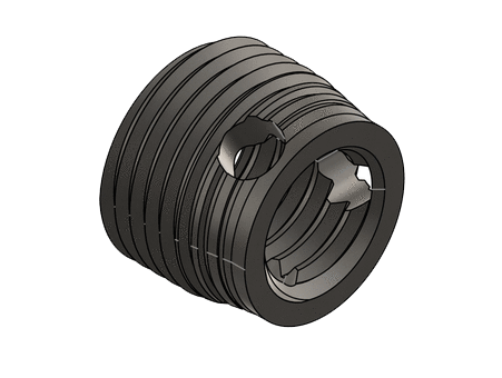
Wood net, cutting slot
Ingénierie des fixations
Grandes Séries – E-Shop
| Part Number | Thread M (6H) | L | Ø E | Well Ø | Fiche technique | 3D |
|---|---|---|---|---|---|---|
| IV 9 030 060 B055 L 0 | M3 X 0.50 | 6 | 5.5 X 1.60 | 4.1 à 4.3 |  | |
| IV 9 035 080 B065 L 0 | M3.5 x 0.60 | 8 | 6.5 x 1.60 | 5.1 à 5.3 | | |
| IV 9 040 100 B070 L 0 | M4 X 0.70 | 10 | 7 X 2.50 | 5.1 à 5.3 | | |
| IV 9 050 120 B090 L 0 | M5 x 0.80 | 12 | 9 x 3.00 | 6.6 à 6.9 | | |
| IV 9 060 140 B100 L 0 | M6 X 1.00 | 14 | 10 X 4.00 | 7.6 à 7.9 | | |
| IV 9 080 200 B130 L 0 | M8 x 1.25 | 20 | 13 x 4.00 | 9.9 à 10.3 | | |
| IV 9 100 230 B160 L 0 | M10 X 1.50 | 23 | 16 X 5.00 | 12.4 à 12.8 | | |
| IV 9 120 260 B190 L 0 | M12 x 1.75 | 26 | 19 x 5.00 | 15.6 à 15.8 | |
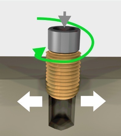
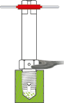
The tool positions the insert along its axis in the moulded well or drilling hole. self-drilling: the material is forced back without making chips self-tapping: the cutting slot cuts the material.
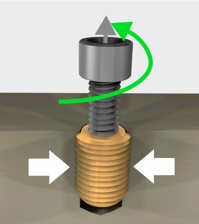
The locknut or the tool mechanism separates the tool and the insert. The material compresses the insert, holding it securely.
Lb Well depth:
To recover the chips produced during installation
Insert length +2 à 3 mm
The insert must be fully buried in the material:
Insert length +1 mm
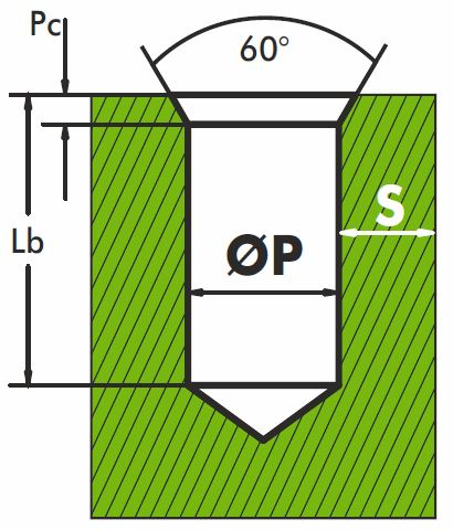
60° chamber
Pc = 1 to 1.5 x ext. thread pitch
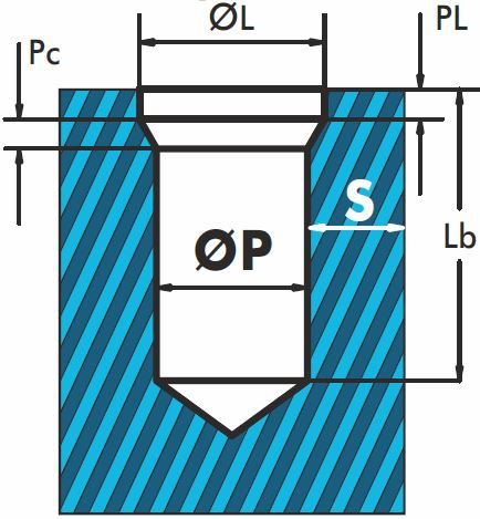
ØL =Ø ext + 0.2 to 0.4 mm
PL =1 à 1.5 x ext. thread pitch
Pc =1 à 1.5 x ext. thread pitch
A larger hole will make it easier to fit the insert but at the expense of the holding force and torque resistance.
Plan a counterbore and/or a chamber to fit the insert more easily an ensure that it is flush with the surface of the material.
Depends on the material elasticity and the stress on the assembly
Commodity plastics:
S ≥ 0.25 to 0.9 insert outer Ø
Technical & high performance plastics & light alloys:
S ≥ 0.2 to 0.6 insert outer Ø
| Internal thread | M2.5 M3 | M4 M5 | M6 M8 | M10 M12 | M14 M16 |
| Speed of rotation in r.p.m. | from 800 to 1300 | from 600 to 900 | from 400 to 700 | from 300 to 450 | from 240 to 350 |


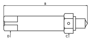
| Référence | Ø | B | D | C |
|---|---|---|---|---|
| OVM 025 CM 0050 A 0 | M2.5 | 55 | 5 | 7 |
| OVM 030 CM 0050 A 0 | M3 | 55 | 5 | 7 |
| OVM 035 CM 0050 A 0 | M3.5 | 60 | 5 | 7 |
| OVM 040 CM 0050 A 0 | M4 | 60 | 5 | 7 |
| OVM 050 CM 0050 A 0 | M5 | 75 | 8 | 13 |
| OVM 060 CM 0050 A 0 | M6 | 75 | 8 | 13 |
| OVM 080 CM 0050 A 0 | M8 | 75 | 8 | 13 |
| OVM 100 CM 0050 A 0 | M10 | 95 | 12.5 | 19 |
| OVM 120 CM 0050 A 0 | M12 | 95 | 12.5 | 19 |
Monter un tourne à gauche sur la partie entrainante de l’outil.Monter l’insert sur l’outil, fente ou trous coupants vers le bas.

Engager l’insert avec une légère pression en début d’installation pour former correctement les premiers filets.

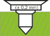
En fin de montage, l’insert doit pénétrer de 0,1 à 0,2 mm ± 1/4 de tour) en dessous de la surface de la pièce.
A l’aide d’une clé, bloquer le contre-écrou et devisser le tourne à gauche pour désolidariser l’insert de l’outil.Le goujon de l’outil se place au milieu de la fente coupante pour ne pas bloquer le dégagement des copaux de coupe.
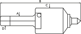
| Référence | Ø | C | A | D | B |
|---|---|---|---|---|---|
| OVA 025 CM 0063 A 0 | M2.5 | 18 | 8 | 6.3 | 78 |
| OVA 030 CM 0063 A 0 | M3 | 18 | 8 | 6.3 | 78 |
| OVA 035 CM 0063 A 0 | M3.5 | 18 | 8 | 6.3 | 78 |
| OVA 040 CM 0063 A 0 | M4 | 18 | 8 | 6.3 | 78 |
| OVA 050 CM 0063 A 0 | M5 | 24 | 12.5 | 10 | 95 |
| OVA 060 CM 0063 A 0 | M6 | 24 | 12.5 | 10 | 95 |
| OVA 080 CM 0063 A 0 | M8 | 24 | 12.5 | 10 | 95 |
| OVA 100 CM 0063 A 0 | M10 | 32 | 16 | 12.5 | 118 |
| OVA 120 CM 0063 A 0 | M12 | 32 | 16 | 12.5 | 118 |
Régler la butée de profondeur de façon à ce que la face d’appui de l’outil pénètre de 0,1 à 0,2 mm en dessous de la surface de la pièce.
Poser l’insert sur le puits.
Fente ou trou coupant vers le bas.
Engager avec un légère pression.
Visser sans pression.

En fin de montage, l’insert doit pénétrer de 0,1 à 0,2 mm ± 1/4 de tour) en dessous de la surface de la pièce.

Produit |
Sous Famille |
Type |
Taraudage |
L |
Forme Extérieure |
Ø E |
Matière |
Spécification |
|||||||
Exemple |
I |
V |
9 |
0 |
3 |
0 |
0 |
6 |
0 |
M |
0 |
5 |
0 |
L |
0 |
|
Insert |
à Visser |
avec fente coupante – pour plastiques tendres et bois |
Taraudage intérieur M3 (1/10 de mm) |
Longueur totale 6 mm (1/10 de mm) |
Filetage Métrique |
Diamètre extérieur 5 mm (1/10 de mm) |
Laiton CW 614N |
Aucune |
|||||||
| Sous Familles V à Visser |
Type d’insert à Visser 1 non fendu – filetage ext. 60°, pas métrique ISO 2 avec fente coupante – filetage ext. 60°, avec pas fin 7 filet à fond plat – avec 3 trous coupants 8 filet à fond plat – avec 3 trous coupants , parois mince 9 avec fente coupante – pour plastiques tendres et bois |
Matières |
Spécifications 0 Aucune 1 ZnNi Zinc Nickel N Nickelage |